Scene Elements
Use
Scenes can comprise and display numerous elements such as bones, scene and object bounding boxes, faces, shadows, surface normals, the scene grid (Legacy layout only), materials, and meshes. Many of these elements are defined as “object elements”. For example, bones, faces, materials, meshes, vertices, edges, and faces.
Elements may be contained within the file itself, or may be added to scenes using SAP 3D Visual Enterprise Author. For example, you can add a cross section plane, cameras, and lights to scenes using the application.
Certain elements can be displayed globally for all viewports or locally in individual viewports, depending on the menu from which you select the command as described below.
Features
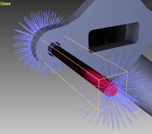
Normals
A flat polygon situated in 3D coordinate space faces a unique direction. An imaginary ray pointing out from the surface of the polygon, and perpendicular to that surface, is called the “normal” of the polygon.
As there will always be two normals, one on each side of the surface, and pointing in opposing directions, the choice of the side from which the normal projects defines the front or “face” of the polygon. In 3D computer graphics, as opposed to the physical world, it is usual for a polygon to have only one face or side, and therefore only one normal. This is because polygons are typically used to create a closed mesh representing the surface of a 3D object and the back side of the polygon is therefore hidden inside the object.
To save render time, polygons are kept single-sided and the normal projects from only the exposed face. However, occasionally it is necessary to create double-sided polygons that have normals pointing from both sides, and which therefore can be rendered from both sides as the different sides come into view during the course of an animation. The face side of a polygon is typically established in a model file by the order in which the vertices of the polygon are listed, clockwise or counterclockwise around the facing (normal) side.
Normals can be associated not only with the flat surfaces of the polygons, but also with the individual points that make up the vertices where polygons meet on the surface of a model. This technique is used in rendering to create the appearance of curved surfaces rather that flat, faceted sides. Such “vertex normals” can be directly assigned in the model file, but are usually computed during rendering by averaging the normals of the adjacent polygons.
Element Colors
You can modify the colors of scene elements. For example, you can display the bounding box in green and the X axis in red.
The elements can then be made visible in the render modes, in the Navigation toolbar. Note that you must also select the related check boxes on the 3D View tab for your color settings to be visible for the object-type elements. For example, the object bounding box, vertices, wireframe, object axes, and surface normals settings.
Changing the color of an element affects all file formats. The default element colors can be restored at any time. Note that colors can only be changed for elements that have been enabled in the original images or model.
You can also modify the default material setting, including the glossiness, specular, and opacity levels.
Element Properties
If an element is also defined as an object, you can modify the properties of that object. For example, materials and the scene’s cross section plane.
Activities
Displaying an Element Globally
Click  Display
  Scene Settings
 in the Navigation toolbar, and then click the element that you wish to display.
Displaying an Element Locally
Right-click the label for the viewport that you wish to modify and elect the element that you wish to display in the viewport
Changing the Color of an Element
-
Do one of the following:
-
Open the Preferences window and, on the Colors tab, double-click the colored square for the element you wish to modify.
-
Open the Scene Properties window and, on the Advanced tab, click the row down arrow for the element you wish to modify.
-
-
Select the color you require and click OK twice.
Restoring the Default Color Settings
Open the Preferences window, select the Colors tab and click Reset.