Illustration Tools
Use
The Illustration tools provide high quality line-art and shading for use in technical documentation for print, Web and multimedia presentations, and is ideal for companies involved with documentation of manufactured products and for presenting 3D images that are clear and concise.
Using Illustration you can create easy to understand illustrations for 3D CAD work in progress, achieve a consistent look and quality throughout documentation, and are able to avoid the retracing of CAD models or photos:
-
Render to raster or vector output
-
Control of edge threshold and line weight
-
Optional use of textures, colors and default materials
-
Parts listing display (Bill of Materials)
-
Use interactive callouts to direct attention to, and identify parts of a model
-
Include BOM within vector illustrations
Features
Raster Illustration
Using this tool, you can create a raster illustration for the current scene and save to various raster different file formats. Scenes are either rendered directly to the active viewport or saved to file based on the settings established using the Properties window.
You can also choose to display the rendered scene in a separate window using the renderer output settings.
Vector Illustration
Using this tool, you can create a vector illustration for the current scene and save it to various vector different file formats
You can establish a number of vector rendering settings using the Vector Illustration window including line thickness, wireframe display, callout rendering, and parts listing inclusion. The options displayed differ depending on the file format you select.
Note that outlines (feature lines) are exported as curves (a solid representation) when rendering to the SVG and AI formats or if the scene includes solids.
Otherwise, all polygonal models export outlines as polylines (a series of line segments). For all other formats, geometry is imported as meshes.
If parts or assemblies are marked as transparent, this is taken into account in vector illustration.
Calculating Intersections
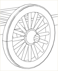
Vectors are normally calculated using triangle edges. You can use the Calculate Intersections option to calculate where triangle intersections are located and output them as vectors if the lines of intersection fall outside of triangle edges when geometry or objects intersect each other. That is, you can draw lines along all face-face intersections.
In the first example, the lines representing the intersection of the spokes with the rim (the inside of the wheel) have not been drawn. Using Calculate Intersections in the second example, the lines have been drawn.

Activities
Rendering a Scene as a Raster Illustration
-
Click the arrow next to the Raster Illustration tool and do one of the following:
-
Choose To Viewport to render the scene directly to the active viewport or to a separate window depending on your renderer output settings. Note that you cannot save the rendered file.
-
Choose To File to render the scene, display the illustration in the viewport, and save it to file.
-
-
Click
 on the Illustration toolbar, make the selections you require and choose Render.
 -
If you selected to display the statistics, click Close to close the dialog after the rendering is complete.
-
Click OK and do one of the following:
-
If you are saving the file, navigate to and select a location in which to save the illustration, enter a name and select a file format, and then click Save.
-
If you are rendering to the viewport, click OK.
-
Rendering a Scene as a Vector Illustration
-
Click
 on the Illustration toolbar and select a file format, in which to save the illustration.
 -
Click Browse, navigate to and select a location to save the illustration, enter a name for the illustration and click Save.
-
Make the selections you require and click Advanced if you want to make further advanced selections.
-
Make the selections you require and click OK.
-
Click Render. The illustration is saved immediately.