Modeling the Data Objects
Modeling the Employee Data Object
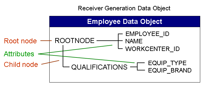
You model the Employee data object as a receiver generation data object. It contains the information required for generating the devices. The devices are generated based on this data object and the customized Receiver Meta Model (RMM). The receiver generation data object contains information about the employee who uses the device. This information includes the employee ID, the work center to which the employee is assigned and his or her qualifications. It has the following structure:
-
Create the Employee data object as a receiver generation data object using the following values:
Field
Value
Comment
Name
EMPLOYEE
Client Specific
Enabled
Default: This indicator is set.
Switch On Automatic Key Mapping
Disabled
Default: This indicator is not set.
Direction
Download Only
For a receiver generation data object, this field is automatically set to the default value Download Only . Receiver generation data objects are used for generating devices and therefore no information is uploaded to the back end.
More information: Creating a New Data Object
-
Create the following nodes for the data object:
The root node ROOTNODE with the following fields:
Field name
Data element
Data type
Length
BE Field
BE Key Field
Comment
NAME
CHAR32
CHAR
32
x
This field is used to retrieve from the back end the name of the user and to write it to the device inventory.
EMPLOYEE_ID
CHAR10
CHAR
10
x
x
This field is used to retrieve from the back end the employee ID of the user and to write it to the device inventory. This field holds the back end key, that is the key under which the back end stores the employee record.
WORKCENTER_ID
CHAR5
CHAR
5
x
This field is used to retrieve from the back end the work center to which the employee is assigned.
NoteThe synchronization key field SYNCKEY is generated automatically for all nodes in all data object categories.
More information: Creating a Data Object Node and
The child node EQUIPMENT with the following fields:
Field name
Data element
Data type
Length
BE Field
BE Key Field
Comment
EQUIP_TYPE
CHAR5
CHAR
5
x
This field is used to retrieve from the back end the type of equipment the employee is qualified to service and to write it to the device inventory.
EQUIP_BRAND
CHAR5
CHAR
5
x
This field is used to retrieve from the back end the equipment brands the employee is qualified to service and to write it to the device inventory.
Note-
The attributes defined in the root node of a receiver generation data object are mapped to single-value attributes in the RMM customizing group. The attributes defined in a child node are mapped to multi value attributes in the RMM customizing group (a receiver generation data object can have one child node). Since the employee can be qualified to service several types and brands of equipment, these attributes are defined in a child node.
-
The synchronization key field PSYNCKEY_MMW is always generated automatically in all child nodes of all data object categories and holds the synchronization key of its parent node.
-
-
Activate the data object.
Modeling the Equipment Data Object
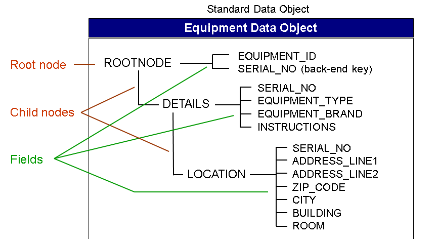
The sample Equipment data object contains all the information the service staff requires for servicing the equipment that is the exact location of the equipment and servicing instructions (PDF file). It has the following hierarchical structure:
-
Create the Equipment data object as a standard data object using the following values:
Field
Value
Comment
Name
EQUIPMENT
Direction
Download Only
Equipment information is to be sent from the back-end application to the service technician's device only; service staff does not change equipment data in the client application to send it to the back end.
Automatic Key Mapping
Enabled
You can set this indicator here as the ROOTNODE, and the DETAILS and LOCATION child nodes contain the same back-end key field.
More information: Automatic Key Mapping
NoteThe Client-Specific and Back-End Access Time stamp indicators have the same settings throughout this tutorial, so they are not mentioned again here and in the following descriptions.
-
Create the following nodes for the data object:
The root node ROOTNODE with the following fields:
Field name
Data element
Data type
Length
BE Field
BE Key Field
Comment
EQUIPMENT_ID
CHAR10
CHAR
10
x
The device's equipment ID defined in the back end.
SERIAL_NO
NUM15
NUMC
15
x
x
The device's serial no. assigned by the manufacturer.
The child node DETAILS with the following fields:
Field name
Data element
Data type
Length
BE Field
BE Key Field
Comment
SERIAL_NO
CHAR15
CHAR
15
x
x
Each node requires at least one back-end key field, therefore we add this field here.
TYPE
CHAR5
CHAR
5
x
For example, PRINT for a printer, SCAN for a scanner (values defined in the back end)
BRAND
CHAR5
CHAR
5
x
Brand values defined in the back end.
Field name
Data type
Length
BE Field
BE Key Field
Binary Memo
Comment
INSTRUCTIONS
RAW-STRING
x
x
Instructions for servicing this equipment (PDF file)
A LOCATION child node to the DETAILS child node with the following fields:
Field name
Data element
Data type
Length
BE Field
BE Key Field
Comment
SERIAL_NO
CHAR15
CHAR
15
x
x
Each node requires at least one back-end key field, therefore we add this field here
ADDRESS_LINE1
CHAR32
CHAR
32
x
Address of the device location
ADDRESS_LINE2
CHAR32
CHAR
32
x
-
ZIP_CODE
NUMC
5
x
-
CITY
CHAR32
CHAR
32
x
-
BUILDING
CHAR32
CHAR
32
x
Building where the device is located
ROOM
CHAR32
CHAR
32
x
Room where the device is located
-
Activate the data object.
Modeling the Customer Data Object
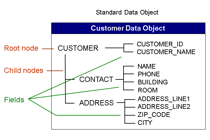
The sample Customer data object contains all the information the service staff requires to find and contact the customer. It has the following hierarchical structure:
-
Create the Customer data object as a standard data object using the following values:
Field
Value
Comment
Name
CUSTOMER
Direction
Download Only
Service staff does not change customer data in the client application
NoteThe Automatic Key Mapping indicator is disabled by default for this and all the following data objects, so it is not mentioned again here and in the following descriptions.
-
Create the following nodes for the data object:
The root node CUSTOMER with the following fields:
Field name
Data element
Data type
Length
BE Field
BE Key Field
Comment
CUSTOMER_NAME
CHAR32
CHAR
32
x
Customer name as defined in the back end
CUSTOMER_ID
CHAR10
CHAR
10
x
x
Customer ID as defined in the back end
A CONTACT child node with the following fields:
Field name
Data element
Data type
Length
BE Field
BE Key Field
Comment
NAME
CHAR32
CHAR
32
x
Name of the contact person for the equipment to be serviced
PHONE
NUMC
15
x
x
Phone number of the contact person
BUILDING
CHAR32
CHAR
32
x
Building and room where the contact person works
ROOM
CHAR32
CHAR
32
x
-
An ADDRESS child node with the following fields:
Field name
Data element
Data type
Length
BE Field
BE Key Field
Comment
ADDRESS_LINE1
CHAR32
CHAR
32
x
Customer address
ADDRESS_LINE2
CHAR32
CHAR
32
x
-
ZIP_CODE
NUMC
5
x
x
-
CITY
CHAR32
CHAR
32
x
-
-
Activate the data object.
Modeling the Service Order Data Object
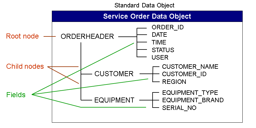
The sample Service Order data object contains all the basic information the service staff requires about the order, that is the name of the customer and the equipment that is involved. It has the following hierarchical structure:
-
Create the Service Order data object as a standard data object using the following values:
Field
Value
Comment
Name
SERVICEORDER
Direction
Bi-Direction
Service order information is to be sent from the back-end application to the service technician's device and back, for example to indicate that the job has been completed.
Conflict Detection Scheme
Last One Wins
To indicate that, in the case of a conflict of incoming data, the last device that sends data wins, meaning the last device's data is saved in the back end.
NoteFor the conflict detection scheme, you could also select First One Wins Object Level or First One Wins Row Level .
-
Create the following nodes for the data object:
The root node ORDERHEADER with the following fields:
Field name
Data element
Data type
Length
BE Field
BE Key Field
Comment
ORDER_ID
CHAR10
CHAR
10
x
x
Service order ID recorded in the back end
DATE
DATS
DATS
8
x
Creation date
TIME
CRTIME
TIMS
6
x
Creation time
STATUS
CHAR1
CHAR
1
x
Order status
USER
CRUSER
CHAR
12
x
User who created the service order
NoteWhen you define an association or a dependency later, you have to identify a field in the specified Link data object that is to contain the synchronization key for this association or dependency. In this tutorial, you create a dependency between the Customer data object and the Service Order data object. In this dependency, you choose the Service Order data object as the Link data object, that is the data object containing the link information. Therefore, you require a field in the Service Order data object to contain the synchronization key for this dependency. You can create this field here (for example as the above listed CUS_SYNCKEY field) or have it created by the system when you define an association. The system automatically creates this key field in the node where the association is defined (here the CUSTOMER child node).
A CUSTOMER child node with the following fields:
Field name
Data element
Data type
Length
BE Field
BE Key Field
Comment
CUSTOMER_NAME
CHAR32
CHAR
32
X
Customer name as defined in the back end
CUSTOMER_ID
CHAR10
CHAR
10
X
x
Customer ID as defined in the back end
REGION
CHAR5
CHAR
5
X
Region the customer belongs to is identified by the zip code (this is used to identify the work center responsible for the customer
CUS_SYNCKEY_MMW
CHAR32
CHAR
32
Optional. Association synchronization key (see above)
An EQUIPMENT child node with the following fields:
Field name
Data element
Data type
Length
BE Field
BE Key Field
Comment
EQUIPMENT_TYPE
CHAR5
CHAR
5
X
For example, PRINT for a printer, SCAN for a scanner (values defined in the back end)
EQUIPMENT_BRAND
CHAR5
CHAR
5
X
Brand values defined in the back end.
SERIAL_NO
NUMC
15
X
x
The device's serial no. assigned by the manufacturer
Add the associations between the Service Order data object and the Customer data object (CUSTOMER_ID field) and between the Service Order data object and the Equipment data object (SERIAL_NO field).
More information: Adding Associations Between Data Objects
-
Activate the data object.
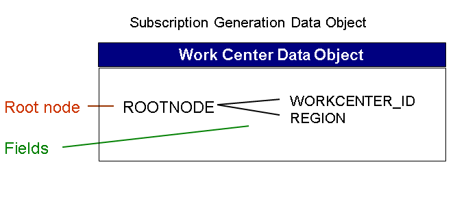
Modeling the Work Center Data Object
You model the Work Center data object as a subscription generation data object to allow for a rule that only retrieves the service orders that apply to a specific work center. The information contained subscription generation data object is only used for retrieving the relevant information and is not transferred to the devices. The Work Center subscription generation data object has the following fields:
-
Create the Work Center data object as a subscription generation data object using the following values:
Field
Value
Comment
Name
WORKCENTER
Direction
Download Only
Only possible option for subscription generation data objects
-
Create the following node for the data object:
The root node ROOTNODE with the following fields:
Field name
Data element
Data type
Length
BE Field
BE Key Field
Comment
WORKCENTER_ID
CHAR5
CHAR
5
x
x
The data type and length must be the same as for the WORKCENTER_ID field in the EMPLOYEE data object.
REGION
CHAR5
CHAR
5
x
x
The data type and length must be the same as for the REGION field in the SERVICEORDER data object.
NoteA subscription generation data object cannot have any child nodes.
-
Activate the data object.
You have modeled all the data objects for the tutorial and can now proceed with customizing the receiver meta model and defining the distribution logic.