Measurements
Use
The measurement tools allow you to measure the distance between a single object or two object elements in a scene, or an angle between elements. For example, between faces, arcs, and vertices of an object. In many cases, these measurements can replace the need for 2D drawings. For example, you can add key measurements to the scene, and you can read key dimensions for manufacturing checks.

Features
When measuring, the elements that can be measured within the object are highlighted when your cursor moves over them. You can limit the types of elements that are highlighted when you measure using the Measurement settings in the Tool Assistant.
Types of Measurement
-
Distance/Perpendicular: Distance measurement is active. All reference features are available.
-
Radius: Radius measurement is active. Reference features Vertex/Endpoint and Arc/Circle are available.
-
Diameter: Diameter measurement is active. Reference features Vertex/Endpoint and Arc/Circle are available.
-
Angle: Angle measurement is active. All reference features are available, except for Line by Two Points and Intersection of Two Lines.
Reference Features
For each type of measurement, reference features are available within that type.
-
Vertex/Endpoint: A corner of a polygon where two edges meet, or of a polyhedron where three or more faces meet. A polyhedron is a three-dimensional solid bounded by polygons. These are displayed as “points” when selected.
-
Edge: Lines of intersection between two faces
-
Edge Midpoint: The measurement selector is enabled for edges and their midpoints. A measurement is created between the midpoints of the selected edges.
-
Face: Planar surfaces of a geometric solid. These surfaces are displayed as white lines surrounding the selected face
-
Arc/Circle: Lines that curve around a face with a center point displayed in a specified color.
-
Line by Two Points: The measurement selector is valid for points, the points are used to set construction lines for the measurement.
-
Quadrant: The measurement selector is only valid for arcs or circles, but can be used with:
-
Distance/Perpendicular
-
Radius
-
Diameter
-
Angle
-
-
Intersection of Two Lines: The measurement selector is enabled for edges. Interconnecting lines can be selected and measured.
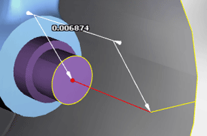
The first element that is measured is displayed as bounded; this determines the bounds of the measurement. For example, the distance is not calculated past the end of an edge, or off the boundary of a face. The second measurement is unbounded. This allows you to measure the distance between a face and a plane or the extension of an edge. For example, in the image below the arc is bounded and the face is unbounded.
Once you perform a measurement, a dimension object is created in the scene. Dimensions are treated in the same way as other objects and can be edited and deleted.
Various settings can also be applied to the measurement tools to determine the way in which the measurements are calculated and displayed. These settings are available in the Tool Assistant, and also in the Create/Edit Measurement Style window.
Measurements are automatically updated as the objects to which they are associated are moved in the scene.
Measurement Rules
Certain rules apply to measurements:
-
Once a measurement is made, the related dimension object is created in the scene
-
Dimensions are markup objects, and as such are displayed in the 3D Objects list when they are created
-
Using the 3D Objects list, you can select, hide and show dimensions, group and collapse their hierarchies, and delete dimensions in the same way as other objects
-
When you rotate, scale, or pan models, the dimensions move in relation to the parts while remaining the same size
-
Dimensions can be moved, rotated, and scaled separately from the model
-
For dimensions to be displayed on an image or model, the Show Markups command must be selected on the Scene Settings menu. The Scene Settings menu is accessed from the Navigation toolbar.